A wire drawing die is a precision tooling component featuring a profiled convergent cavity, used to reduce the cross-sectional area of metal wire. Wire is pulled through this profile under mechanical tension, undergoing plastic deformation to reach an exact diameter and surface finish. Coolervie manufactures these dies to strict tolerances to control wire breakage and maximize drawing machine yield.
Structural Anatomy
A drawing die is a composite assembly engineered to manage extreme mechanical and thermal loads.
The Casing
The outer shell, forged from high-grade steel or stainless steel, provides physical containment. It dissipates the thermal energy generated by friction and deformation, and counteracts the intense radial pressures expanding outward from the core.
The Cylindrical Insert
The core insert is the functional center of the die. Its foundational geometry is strictly cylindrical. This specific shape is an engineering requirement to guarantee symmetrical radial stress distribution when pressed into the casing. A perfectly cylindrical insert maintains absolute concentricity, preventing asymmetrical wear and structural failure under high-speed drawing conditions.
The Inner Profile
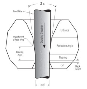
The internal cavity of the cylindrical insert is machined into five distinct operational zones:
-
Entrance (Bell): Channels the incoming wire and directs drawing lubricant into the core.
-
Approach (Lubrication Zone): Pressurizes the dry or wet lubricant onto the wire surface before deformation.
-
Reduction Angle (Compression Zone): The area where transverse compressive forces initiate plastic deformation and area reduction.
-
Bearing (Sizing Zone): A calibrated straight section that locks in the final wire diameter and micron-level tolerances (e.g., exactly 0.197mm).
-
Back Relief (Exit Zone): A diverging angle that prevents mechanical abrasion and shaving as the wire exits the die block.
Mechanics of the Drawing Process
Wire drawing operates on the principle of volumetric constancy during cold plastic deformation. As the machine’s capstan applies a tensile pull, the die’s reduction angle applies a corresponding transverse compressive force.
To maintain continuous operation, the pulling force must exceed the metal’s yield strength to force deformation, but remain strictly below the ultimate tensile strength of the exiting wire section. Exceeding this limit causes necking and immediate wire breakage. Lubrication systems within the die box are required to maintain a hydrodynamic fluid film, mitigating metal-on-metal friction and thermal degradation of the die profile.
Production Metrics Control
In continuous wire manufacturing operations, the drawing die dictates three primary output metrics:
-
Dimensional Tolerance: The bearing length and diameter control gauge consistency across long production runs.
-
Surface Finish: The internal polish of the die profile dictates the wire’s surface roughness (Ra), which is mandatory for downstream processes like enameling, plating, or extrusion coating.
-
Mechanical Properties: The cold working process alters the internal grain structure of the metal. Calculating the exact area reduction percentage per pass allows engineers to control the work hardening rate and the final tensile strength of the wire.
Die Material Specifications
The material composition of the cylindrical insert is selected based on the metal being drawn and the target production volume:
-
Polycrystalline Diamond (PCD): High wear resistance and thermal conductivity for continuous, high-speed drafting.
-
Natural Diamond (ND): Provides the lowest surface friction for ultra-fine wire applications demanding a mirror finish.
-
Single Crystal Synthetic Diamond (SSCD): Engineered for highly predictable wear patterns and uniform bore expansion.
-
Tungsten Carbide (TC): Delivers high fracture toughness for drawing ferrous metals, steel cord, and primary roughing passes.
Drafting Sequence Integration
Multi-pass drawing sequences require exact mathematical modeling to synchronize machine capstan speeds with the wire’s elongation.
When utilizing tools like the Coolervie Online Die Drafting Calculator to map a sequence, kinematic variables dictate the parameters. For high-speed drawing machinery, a specific slip factor (typically around 2%) must be integrated into the block calculations. This slip factor must be applied continuously across the entire machine drafting sequence, right down to the final finishing die, to prevent tension spikes and subsequent wire breaks.